Vacuum Sewers


- Compiled by:
- Beat Stauffer (seecon international gmbh)

Source: http://www.sswm.info/category/implementation-tools/wastewater-collection/hardware/sewers/vacuum-sewers


References
Executive Summary
Vacuum sewerage systems consist of a vacuum station, where the vacuum is generated, the vacuum pipeline system, collection chambers with collection tanks and interface valve units. In contrast to conventional gravity sewerage systems with intermediate pumping stations, the permanent pressure within the vacuum system is maintained below atmospheric pressure. Moreover, vacuum technology reduces water consumption considerably, enabling flexible installations regardless of topography and water availability. In addition, it allows for the use of alternative wastewater handling (blackwater and greywater separation).
| In | Out |
|---|---|
Basic Design Principles
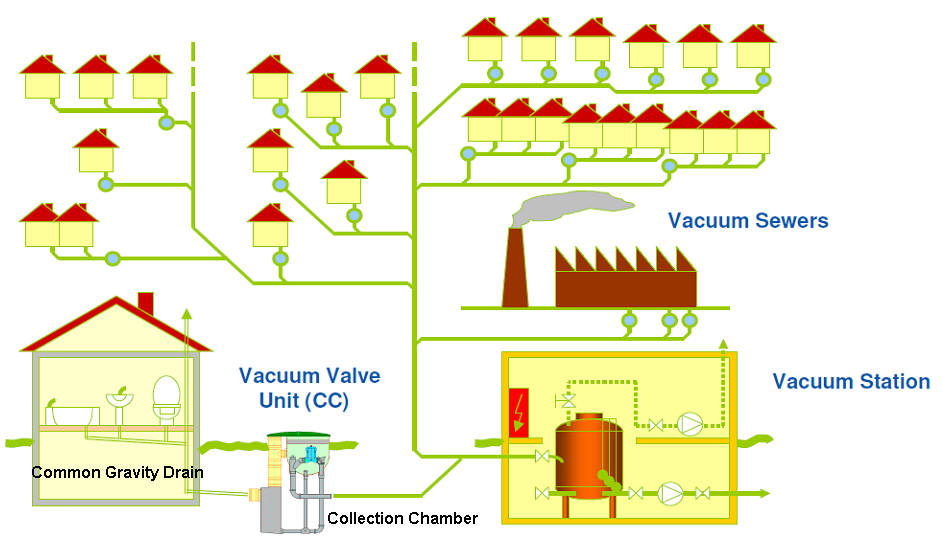
Vacuum sewerage systems use a central vacuum source to convey sewage from individual households to a central collection station (UNEP 2002). It is a mechanised system ofwastewater transport. Unlike gravity flow (e.g.conventional sewers,separate sewers or simplified sewers), vacuum sewers use differential air pressure (negative pressure) to move the sewage. A central source of power to operate vacuum pumps is required to maintain vacuum (negative pressure) on the collection system. The system requires a normally closed vacuum/gravity interface valve at each entry point to seal the lines so that vacuum can be maintained. These valves, located in valve pits, open when a predetermined amount of sewage accumulates in collecting sumps. The resulting differential pressure between atmosphere and vacuum becomes the driving force that propels the sewage towards the vacuum station (PDH ENGINEER 2007).
Transport of Wastewater
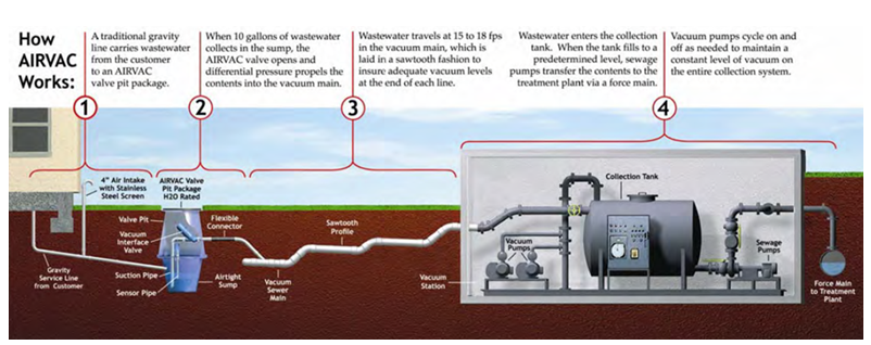
A traditional gravity line carries wastewater down to the collection chamber (it is recommended to combine it with vacuum- or low-flush toilets). As soon as the level reaches a defined height, thevacuum interface valve opens and the negative pressure sucks the wastewater into thevacuum sewer main. At the end of the pipe system, there is a collection tank. When the tank fills to a predetermined level, sewage pumps transfer the contents to a treatment plant via aconventional or separate sewer system. It is important to understand that the collection system is hold on permanent level of vacuum.
Collection Chamber
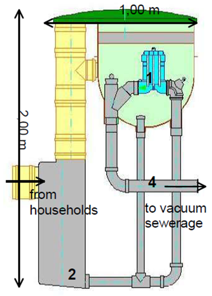
The wastewater from the houses is held back in collection chambers, with pneumatic regulating valves close to the houses. When a given volume of wastewater is collected in the chamber sump, a pneumatic controller is activated by hydrostatic pressure. The controller opens an interface valvefor an adjustable time period. The wastewater (10 to 50 L) and a certain amount of air (20 to 60 L) are evacuated through the open valve into the vacuum sewer line. The pressure gradient between the vacuum station and atmospheric pressure at the collection pits is responsible for the movement of sewage to the vacuum tank (GTZ 2005).
Vacuum Station
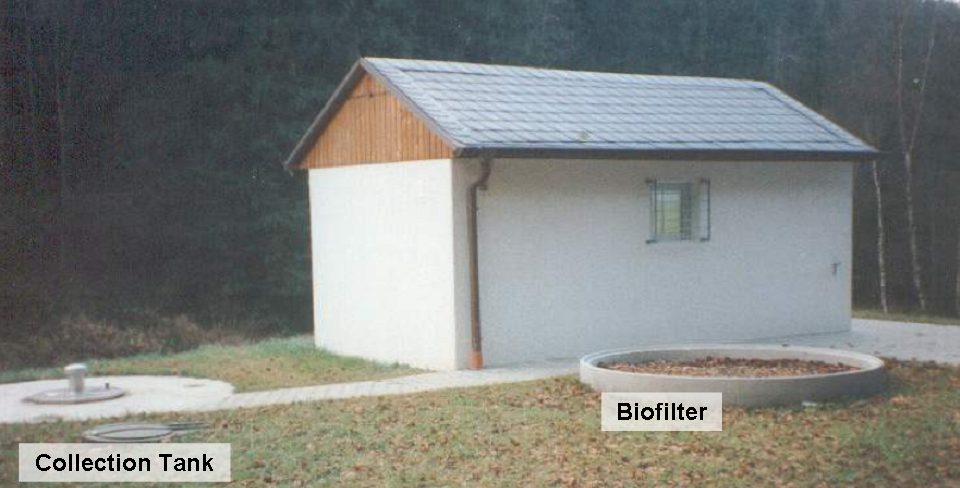
All the vacuum sewers are connected to the vacuumcollection vessel installed at the central vacuum station, where vacuum pumps create the required negative pressure (approximate -0.6 bar). The vacuum vessel can be placed inside or buried outside the vacuum station. Transfer pumps convey thewastewater from the vessel to the wastewater treatmentplant or to an existing sewer. The capacity and dimensions of the vacuum station are dictated by the particular requirements of the sewer system. Operation of the vacuum and transfer pumps is controlled by a software (ROEDIGER 2007).
Piping
In contrast to gravity sewer pipes, it is easier and cheaper to build the vacuum sewer piping. Nomanholes or sewer pumping stations are necessary, just inspection points for pressure testing. This avoids settling of sludge and no manholes are needed to be cleaned out (see also dignity orhuman powered emptying). The pipes of a vacuum sewer system have a smaller diameter (80 to 250 mm) and the trenches are narrow and shallow (1.0 to 1.2 m). That is also an advantage if there is a high groundwater table. Unexpected obstacle can easily be bypassed by a modified and more flexible pipe design. If a pipe is damaged, the risk of sewage infiltration is very low, because of the negative pressure in the sewer line. Expert design is required, but the construction and installation work can be done by local contractors and pipe suppliers. No heavy machinery is necessary and there is no danger of a collapse of deep trenches (ROEDIGER 2007).

Costs Considerations
As it is a high-tech system, it is costly. But in comparison with a conventional sewer system, it is cheaper. Piping costs are lower, because the dimensions are smaller. Therefore, less material is required. Also the installation can be cheaper because piping is independent from the topography. Furthermore, no heavy machinery is necessary for excavate deep trenches, thus the work can be done by local workers, which creates employment. Finally, big amounts of flushing water can be saved which is economical and ecological reasonable. However, the constantenergy requirement for the permanent vacuum generation can increase the costs.
Operation and Maintenance
The risk of clogging is low and there is almost no cleaning/emptying work to do. From time to time pressure in the vacuum sewer system should be tested. The system needs instructed workers for maintenance and operation works. More complex and/or technical problems are in the responsibility of the manufacturer.

Construction of a sewer at the left side and pressure testing et the right side. Source: ROEDIGER (2007)
Health Aspects
As long as it is maintained properly, a vacuum sewer system guarantees a high level of comfort and hygiene. There is a very low risk of contamination due to leakage. It is a closed system, thus there is almost no contact between wastewater and operators. However, a treatment system at the end of the pipe needs to be in place.
At a Glance
Working Principle
| |
Capacity/Adequacy
|
Can be used in dense populated areas as well as in rural areas. It is independent from the topography (hilly or flat area) and can pass any obstacles without any problems
|
Performance
|
Very high performance
|
Costs
|
High capital costs, but still lower than gravity sewer system
|
Self-help Compatibility
|
Very low
|
It is a reliable system and does not need a lot of maintenance
| |
Reliability
|
Very reliable
|
Main strength
|
Shallow trenches and it requires a minimal amount of flushing water. Very high level of comfort and hygiene.
|
Main weakness
|
It is costly and it needs a permanent energy source for the vacuumpumps. It needs expert design and depends on a centralised system.
|
Applicability
Basically, vacuum sewering is most suitable in areas where a collection is needed but other options are too costly or not feasible (Adapted from HUBA & PANZERBIETER 2006);
- Flat topography: gravity systems demand installation at great depths to maintain adequate flow (pump stations, lift stations)
- Rock layers, running sand or a high groundwater table make deep excavation difficult
- Areas short of water supply or poor communities that must pay for and cannot afford great amounts of water necessary for operation of gravity systems
- Areas that are ecologically sensitive
- Areas where flooding can occur
- Areas with obstacles to a gravity sewer route
- Installation of a new fresh water network, allowing sewerage pipe installation in the same trench
Where potable water is in short supply and/or people are poor, flushing velocities in gravitysewers are often difficult to attain and maintain. A vacuum system relies on the negative pressure to propel the liquid at scouring velocities and it is largely independent of the volumes of water used.
Advantages
- Requires less water to transport the excreta and faeces to the centralised treatment system
- Considerable savings in construction costs, and much shorter construction period
- Piping: Pipelines laid in shallow and narrow trenches; small diameter pipelines, flexible pipeline construction, easy to lay pipelines around obstacles
- Sewers and water mains can be laid in a common trench
- Closed systems with no leakage or smell
- No manholes along the vacuum sewers
- One central vacuum station can replace several pumping stations
Disadvantages
- Needs expert design
- Needs energy to create the permanent vacuum
- Relatively high capital costs
- Recycling of nutrients and energy becomes difficult
- Unsuitability for self-help, requires skilled engineers operators
- It is still a flushing system which transports wastewater away. If there is no treatment plant and an unprofessional discharge it can contaminate the environment
References 
GTZ (Editor) (2005): Vacuum Technology (Low Pressure Systems). Eschborn: German Agency for Technical Cooperation (GTZ) GmbH. PDF
HUBA-MANG, E.; PANZERBIETER, T. (2006): Sanitation is more than Life - Sustainable Sanitation Options for Sri Lanka. Singapore: World Toilet Organization (WTO). PDF
PDH ENGINEER (Editor) (2007): Vacuum Sewers: Design and Installation Guidelines. Alexandria, Virginia: Water Environment Federation. URL [Accessed: 09.03.2011]. PDF
ROEDIGER (Editor) (2007): RoeVac Vacuum Sewer System. Hanau: Roediger Vacuum GmbH. URL[Accessed: 09.03.2011]. PDF
UNEP (Editor) (2002): A Directory of Environmentally Sound Technologies for the Integrated Management of Solid, Liquid and Hazardous Waste for Small Island Developing States (SIDS) in the Pacific Region. The Hague: United Nations Environment Programme (UNEP). URL [Accessed: 28.03.2012]. PDF
ROEDIGER (Editor) (2007): RoeVac Vacuum Sewer System. PDF Presentation. Hanau: Roediger Vacuum GmbH. PDF


